If you have different hardware that you want to use, you can find a Python server that can act as a Lunar sensor here: Lunar Sensor
You can run the server on any device, as long as you have a way to read lux values.
Use cases
- Raspberry Pi with an I²C sensor
- Home Assistant server with a light sensor
- HomeKit sensor with a local API
- Other USB light sensors
Note: this server is not needed for the instructions below this section
There are 2 possible solutions, based on how much effort you're willing to put into the sensor and how much you care about the price and looks.
Solution 1: No-solder sensor
Characteristics
- Clean
- Easy to make
- Readily available parts
- Expensive
- A bit bulky
Components
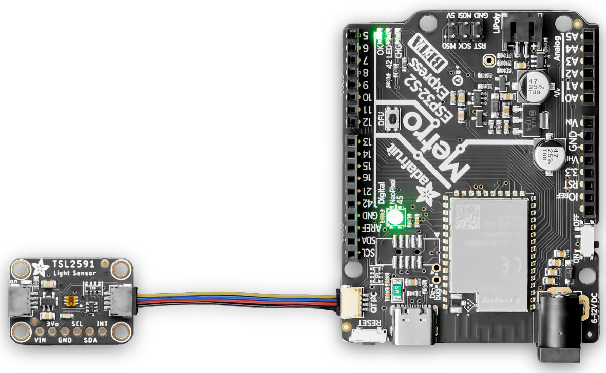
Assembly
- Connect one end of the Stemma QT cable to the QT connector of the Metro ESP32-S2 board
- Connect the other end of the Stemma QT cable to any of the QT connectors of the TSL2591 sensor
Enter ROM Bootloader Mode
Entering the bootloader is easy. Complete the following steps.
- Make sure your ESP32-S2 is plugged into USB port to your computer using a data/sync cable. Charge-only cables will not work!
- Turn on the On/Off switch - check that you see the OK light on so you know the board is powered, a prerequisite!
- Press and hold the DFU / Boot0 button down. Don't let go of it yet!
- Press and release the Reset button. You should have the DFU/Boot0 button pressed while you do this.
- Now you can release the DFU / Boot0 button
- Check your computer for a new serial port (on macOS it appears as a file beginning with
/dev/cu.usb)
- Run this in a terminal to list possible serial ports:
ls -l /dev/cu.usb*
Now you can start firmware installation by following the steps here: Firmware Installation
Notes:
If you tried installing the firmware on versions before Lunar v4.7.0
- Remove the cache first:
rm -r ~/.platformio
- Retry the firmware installation process
The ESP32 chip only supports 2.4Ghz networks, don't try to make it connect to a 5Ghz network
Solution 2: Solder or wire-through-hole
Characteristics
- Cheap
- Compact
- Not so clean looking
- Needs a bit more manual work
- Parts are not always in stock
Components
- Any ESP32/ESP8266 dev board (pick one that is cheapest and available at your location)
- ESP32 Boards without pin headers soldered:
- ESP32 Boards with pin headers already soldered:
- ESP8266 Boards without pin headers soldered:
- ESP8266 Boards with pin headers already soldered:
- Adafruit TSL2591 High Dynamic Range Digital Light Sensor [STEMMA QT] : ID 1980 : $6.95
- STEMMA QT cable based on the ESP32/ESP8266 board chosen:
- For boards without pin headers soldered:
- For boards with pin headers soldered:
Assembly for ESP32 boards
- Connect one end of the Stemma QT cable to any of the QT connectors of the TSL2591 sensor
- Route the wires as the following:
- Black wire to ground (the pin marked with G)
- Red wire to 3 volts (the pin marked with 3V)
- Blue wire to pin 19
- Yellow wire to pin 23
- Connect the wires:
- If the board has holes (no pin headers soldered): Insert the male header of each wire into the pin hole and:
- either solder the pin to the hole
- ...or bend the pin around the hole so that it always makes contact with the metal around the hole and stays in place
- If the board has pin headers soldered: Insert each pin into the female header of each wire
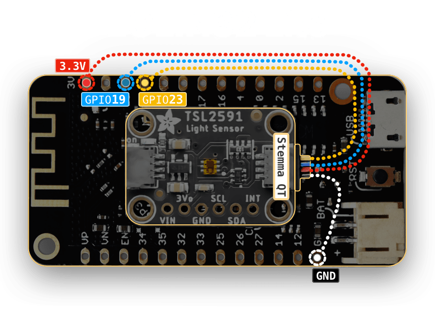
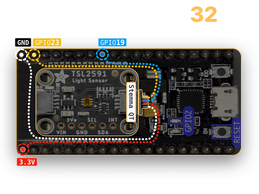
| ESP32 Pin |
TSL2591 Pin |
| 23 |
SCL |
| 19 |
SDA |
| 3V |
VIN |
| G |
GND |
Assembly for ESP8266 boards
- Connect one end of the Stemma QT cable to any of the QT connectors of the TSL2591 sensor
- Route the wires as the following:
- Black wire to ground (the pin marked with GND )
- Red wire to 3 volts (the pin marked with 3V3)
- Blue wire to GPIO4 (the pin marked with D2 on NodeMCU and Wemos D1 Mini)
- Yellow wire to GPIO5 (the pin marked with D1 on NodeMCU and Wemos D1 Mini)
- Connect the wires:
- If the board has holes (no pin headers soldered): Insert the male header of each wire into the pin hole and:
- either solder the pin to the hole
- ...or bend the pin around the hole so that it always makes contact with the metal around the hole and stays in place
- If the board has pin headers soldered: Insert each pin into the female header of each wire
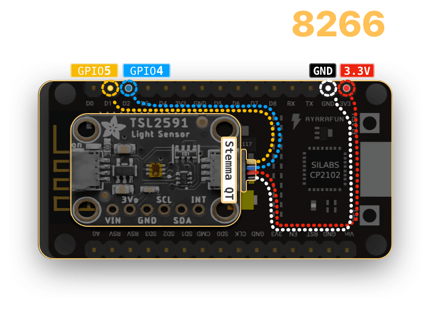
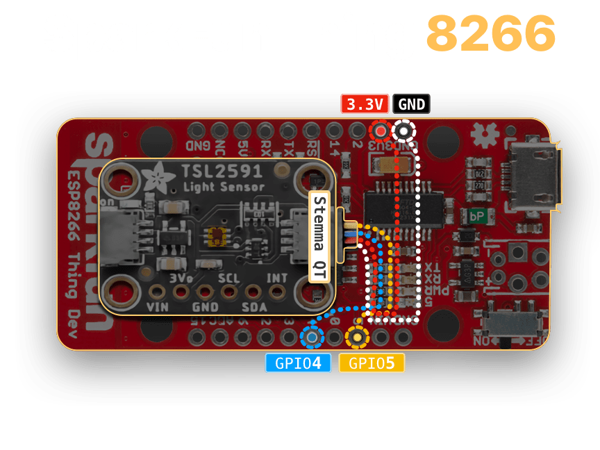
| ESP8266 Pin |
TSL2591 Pin |
| D1 |
SCL |
| D2 |
SDA |
| 3V3 |
VIN |
| GND |
GND |
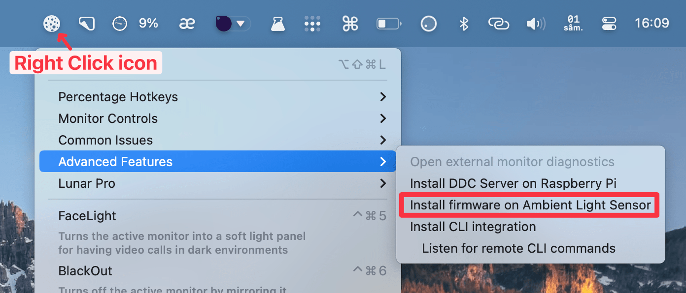
Lunar has an automated process for installing the firmware on ESP32/ESP8266 boards.
Click on Install firmware on Ambient Light Sensor in the Lunar menu to start the process:
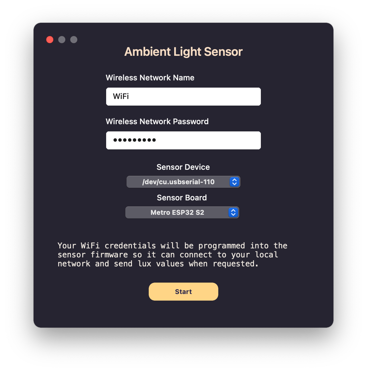
Parameters
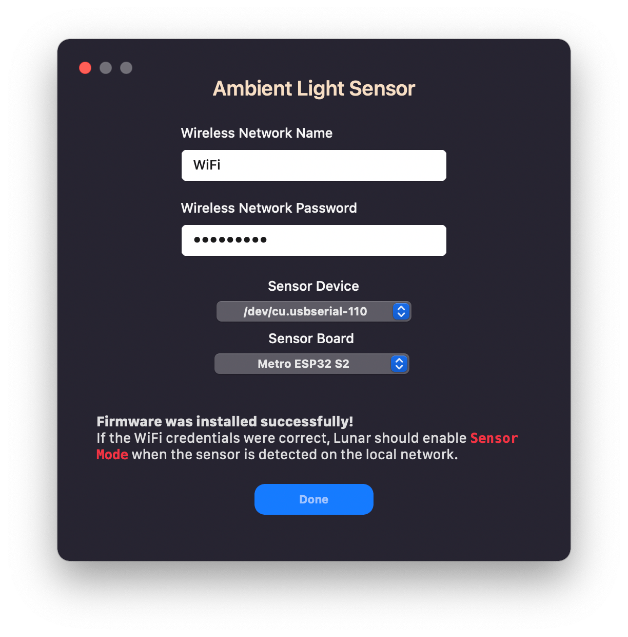
A small window with firmware parameters will appear.
- WiFi credentials
- Name and password of the wireless network where your ESP32/ESP8266 should connect
- Choose the same network where your Mac device is connected
- Sensor Device to flash
- This is either a filesystem path beginning with
/dev/cu.usb or a network hostname like lunarsensor.local
- After the device is flashed and running on the local network, you can update it over-the-air (no USB needed) using the
lunarsensor.local hostname
- Sensor Board type
- This is the type of ESP32/ESP8266 board that you want to flash
- Generic ESP32 works for most of the ESP32 boards as long as you're sure it's not an
ESP32-S2 processor
Installing
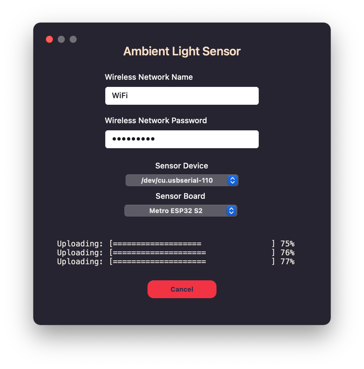
After clicking the Start button, Lunar will begin a three step process:
- Fetch all firmware dependencies and compilers from the internet
- Compile the firmware
- Upload the firmware to the board
Installation done
If the installation finished successfully, you will see a message as in the image below.
You can click on the Done button to close the window and let Lunar search for the sensor on the local network.
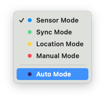
Sensor Mode Detection
If the sensor booted into the new firmware and connected to the local network, you will notice that Lunar has made Sensor Mode available in the mode dropdown from the top-right part of the Lunar window.
You can click on it to activate it, or choose Auto Mode if you want Lunar to automatically fallback to other modes if the sensor becomes unavailable.
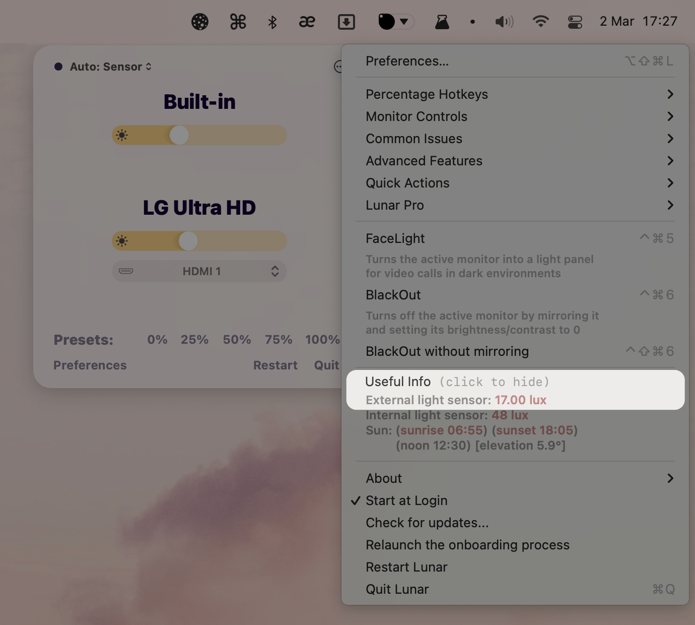
Lux value
When Sensor Mode is activated, you can also see the current ambient light around the sensor in the Lunar menu.
Error on flashing the firmware
If you get an error on the firmware installation process, you should see a View logs button. Click it to open the logs in a log viewer.
You can also view the logs manually by opening /tmp/lunar-sensor-install.log in any text editor.
If you don't understand the error from the logs, you can upload them on Lunar's Discord community and I'll take a look.
If you understand the error, you may try to tweak the firmware:
- Open a Terminal
- Copy the firmware files in a separate folder:
mkdir -p ~/lunarsensor && cd ~/lunarsensor
cp /Applications/Lunar.app/Contents/Resources/{*.yaml,install.sh} ~/lunarsensor/
- Open
lunar.yaml in a text editor and tweak it for your own board
- Manually flash the firmware
WIFI_SSID="your wifi name" WIFI_PASSWORD="your wifi password" ESP_DEVICE="your esp32/esp8266 device path or host" BOARD="your esp32/esp8266 board type" ./install.sh
Example:
WIFI_SSID="PrettyFly" WIFI_PASSWORD="for a wifi" ESP_DEVICE="/dev/cu.usbserial-110" BOARD="esp32dev" ./install.sh
Lunar doesn't detect the sensor
First check if the sensor booted and connected to the local network:
- If the ESP32/ESP8266 board has flashing lights, that means the board is booted and running firmware code (although we can't say for sure if it's the correct code)
- Open a Terminal and try to ping the sensor
- Run the following command:
ping lunarsensor.local
- If you see lines like
64 bytes from 192.168.1.237 then the device is connected to your WiFi
- Otherwise, it's possible that the WiFi credentials were incorrectly written
- Try the firmware installation again and pay close attention to the network name and password inputs
- If the device can be pinged, check the sensor output
Run the following command and wait about 10 seconds
curl -N lunarsensor.local/events
You should start seeing lines like the following:
data: {"id":"sensor-ambient_light_tsl2561","state":"0.1 lx","value":0.0912}
If instead you don't get any output or see a lot of NaN values like:
data: {"id":"sensor-ambient_light_tsl2591","state":"nan","value":NaN}
- It is possible that the TSL25x1 sensor is not connected correctly (or even faulty)
- Take a look at the Assembly instructions again and try to redo the wire connections
